| Item | Dimension | Unit |
|---|---|---|
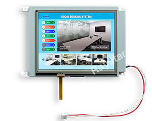
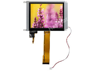
| TFT Series | Bar Type TFT, TFT Panel with Controller Board | |
| Size (Diagonal) | 5.2 | inch |
| Dot Matrix / Resolution | 480 × RGB × 128 | dots |
| Module Dimension | 180.0 × 65.0 × 8.8 | mm |
| Active Area | 127.152 × 33.9072 | mm |
| Dot / Pixel Pitch | 0.0883 × 0.2649 | mm |
| LCD Type | TFT, Normally White, Transmissive | |
| View Direction | 6 o’clock | |
| Gray Scale Inversion Direction | 12 o’clock | |
| Aspect Ratio | Bar Type | |
| Backlight Type | LED, Normally White | |
| Control Board | Yes | |
| TFT Driver IC | SSD1963 | |
| Interface | Digital 8080 family MPU 8bit/16bit | |
| Touch Panel | Without Touch Panel | |
| Surface | Glare | |
| Brightness | 400 | cd/㎡ |
| O-Film | Yes | |
| Mounting Hole | Yes | |
| Operating Temperature | -20~+70 | °C |
| Storage Temperature | -30~+80 | °C |
| Pin | Symbol | Function |
|---|---|---|
| 1 | GND | System round pin of the IC. Connect to system ground. |
| 2 | VDD | Power Supply : +3.3V |
| 3 | BL_E | Backlight control signal , H: On \ L: Off |
| 4 | D/C | Data/Command select |
| 5 | WR | Write strobe signal |
| 6 | RD | Read strobe signal |
| 7 | DB0 | Data bus |
| 8 | DB1 | Data bus |
| 9 | DB2 | Data bus |
| 10 | DB3 | Data bus |
| 11 | DB4 | Data bus |
| 12 | DB5 | Data bus |
| 13 | DB6 | Data bus |
| 14 | DB7 | Data bus |
| 15 | DB8 | Data bus (When select 8bits mode, this pin is NC) |
| 16 | DB9 | Data bus (When select 8bits mode, this pin is NC) |
| 17 | DB10 | Data bus (When select 8bits mode, this pin is NC) |
| 18 | DB11 | Data bus (When select 8bits mode, this pin is NC) |
| 19 | DB12 | Data bus (When select 8bits mode, this pin is NC) |
| 20 | DB13 | Data bus (When select 8bits mode, this pin is NC) |
| 21 | DB14 | Data bus (When select 8bits mode, this pin is NC) |
| 22 | DB15 | Data bus (When select 8bits mode, this pin is NC) |
| 23 | NC | No connect |
| 24 | NC | No connect |
| 25 | CS | Chip select |
| 26 | RESET | Hardware reset |
| 27 | LR | Right /Left selection; Default R/L is Pull High |
| 28 | UD | Up/down selection; Default U/D is Pull High |
| 29 | NC | No connection |
| 30 | NC | No connection |
| 31 | NC | No connection |
| 32 | NC | No connection |
| 33 | VLED- | VLED- for B/L LED inverter (GND) |
| 34 | VLED- | VLED- for B/L LED inverter (GND) |
| 35 | VLED+ | VLED+ for B/L LED inverter (+5V) |
| 36 | VLED+ | VLED+ for B/L LED inverter (+5V) |
| Pin | Symbol | Function |
|---|---|---|
| 1 | NC(FG) | No connect (Frame Grand) |
| 2 | GND | System round pin of the IC. Connect to system ground. |
| 3 | VDD | Power Supply : +3.3V |
| 4 | BLE | Backlight control signal , H: On \ L: Off |
| 5 | WR | Write strobe signal |
| 6 | RD | Read strobe signal |
| 7 | CS | Chip select |
| 8 | D/C | Data/Command select |
| 9 | NC | No connect |
| 10 | RESET | Hardware reset |
| 11 | DB0 | Data bus |
| 12 | DB1 | Data bus |
| 13 | DB2 | Data bus |
| 14 | DB3 | Data bus |
| 15 | DB4 | Data bus |
| 16 | DB5 | Data bus |
| 17 | DB6 | Data bus |
| 18 | DB7 | Data bus |
| 19 | NC | No connect |
| 20 | NC | No connect |
| 21 | VLED+ | VLED+ for B/L LED inverter (+5V) |
| 22 | VLED- | VLED- for B/L LED inverter (GND) |
| 23 | NC | No connect |
| 24 | NC | No connect |
| 25 | NC | No connect |
| 26 | GND | Hardware reset |

| Item | Symbol | Min | Typ | Max | Unit |
|---|---|---|---|---|---|
| Operating Temperature | TOP | -20 | - | +70 | ℃ |
| Storage Temperature | TST | -30 | - | +80 | ℃ |
| Item | Symbol | Condition | Min | Typ | Max | Unit |
|---|---|---|---|---|---|---|
| Supply Voltage For LCM | VDD | - | 3.0 | 3.1 | 3.3 | V |
| Supply Current For LCM | IDD | - | - | 200 | — | mA |
| Parameter | Symbol | Min | Typ | Max | Unit |
|---|---|---|---|---|---|
| Operation Current For LED Driver | VLED=5V | - | 250 | - | mA |
| Supply Voltage For LED Driver | VLED+ | - | 5 | - | V |
| LED Life Time | - | 50,000 | - | Hr |