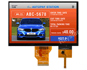
| Item | Dimension | Unit |
|---|---|---|
| TFT Series | IPS TFT LCD,Support HDMI Signal TFT | |
| Size (Diagonal) | 7 | inch |
| Dot Matrix / Resolution | 1024 × RGB × 600 (TFT) | dots |
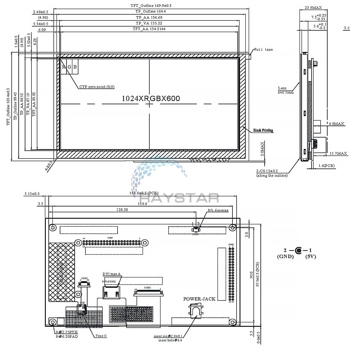
| Module Dimension | 169.9 (W) × 103.4 (H) × 23.9 (D) | mm |
| Active Area | 154.2144 × 85.92 | mm |
| Dot / Pixel Pitch | 0.1506 × 0.1432 | mm |
| LCD Type | TFT, Normally Black, Transmissive | |
| View Direction | 85/85/85/85 (IPS) | |
| Backlight Type | LED, Normally White | |
| Control Board | Yes | |
| Power Board | Yes | |
| Built-in Controller | LT6911C | |
| Interface | DVI (HDMI CN) | |
| PCAP FW Version | 0x07.0x00.0x00.0x00.0x65.0x90.0x00.0x01 | |
| PCAP IC | ILI12130 | |
| PCAP Interface | USB | |
| PCAP Resolution | 16384*16384 | |
| Detect Points | 1 | Points |
| Touch Panel | Projected Capacitive Touch Panel, PCAP | |
| Surface | Glare | |
| Brightness | 450 | cd/㎡ |
| O-Film | No | |
| Operating Temperature | -20~+70 | °C |
| Storage Temperature | -30~+80 | °C |
| Pin No. | Symbol | Function |
|---|---|---|
| A1 | GND | Power Ground |
| A4 | NC | No connection |
| A5 | NC | No connection |
| A6 | D+ | Data line + |
| A7 | D- | Data line - |
| A8 | NC | No connection |
| A9 | NC | No connection |
| A12 | GND | Power Ground |
| B12 | GND | Power Ground |
| B9 | NC | No connection |
| B8 | NC | No connection |
| B7 | D- | Data line - |
| B6 | D+ | Data line + |
| B5 | NC | No connection |
| B4 | NC | No connection |
| B1 | GND | Power Ground |
| Pin No. | Symbol | Function |
|---|---|---|
| 1 | 5V | Power Supply (5V) |
| 2 | GND | Ground |
| 3 | NC | No connection |
| Pin No. | Symbol | Function |
|---|---|---|
| 1 | PWM | Light Dimming Control(PWM) Input Voltage (bright in 0% dark in 100%) |
| 2 | GND | Ground |
| Pin No. | Symbol | I/O | Function |
|---|---|---|---|
| 1 | Rx2+ | I | Channel-2 positive receiver input; low-voltage signal differential- input pair. |
| 2 | GND | P | Ground |
| 3 | Rx2- | I | Channel-2 negative receiver input; low-voltage signal differential- input pair. |
| 4 | Rx1+ | I | Channel-1 positive receiver input; low-voltage signal differential- input pair. |
| 5 | GND | P | Ground |
| 6 | Rx1- | I | Channel-1 negative receiver input; low-voltage signal differential- input pair. |
| 7 | Rx0+ | I | Channel-0 positive receiver input; low-voltage signal differential- input pair. |
| 8 | GND | P | Ground |
| 9 | Rx0- | I | Channel-0 negative receiver input; low-voltage signal differential- input pair. |
| 10 | RxC+ | I | Clock positive receiver input; low-voltage signal differential- input pair. |
| 11 | GND | P | Ground |
| 12 | RxC- | I | Clock negative receiver input; low-voltage signal differential- input pair. |
| 13-14 | NC | - | No connection |
| 15 | SCL | I/O | DDC(Data Display Channel) Clock |
| 16 | SDA | I/O | DDC(Data Display Channel) Data |
| 17 | GND | P | Ground |
| 18 | 5V | P | Power Supply |
| 19 | Detect | I/O | Hot plug detect |
I: input, O: output, P: Power
| Item | Symbol | Min | Typ | Max | Unit |
|---|---|---|---|---|---|
| Operating Temperature | TOP | -20 | - | +70 | ℃ |
| Storage Temperature | TST | -30 | - | +80 | ℃ |
| Item | Symbol | Min | Typ | Max | Unit |
|---|---|---|---|---|---|
| Supply Voltage For LCM | VDD | 4.9 | 5.0 | 5.1 | V |
| Supply Current For LCM | IDD | - | 1,470 | 2,205 | mA |
| LED Life Time | - | 50,000 | - | - | Hr |
| Parameter | Symbol | Min | Typ | Max | Unit |
|---|---|---|---|---|---|
| PWM Control Level (Backlight PWM) | High Level | - | 3.3 | - | V |
| Low Level | - | 0 | - | V | |
| PWM Control Frequency | - | - | 1K | - | Hz |